
by Tom Carnegie-November 2004
I have just about (but not quite) run out of things to write about in regard
to making models T's go faster in the Montana 500. I am withholding some
information that I may or may not spill later on when I'm no longer serious
about competing. I don't know when that day will come. In the mean time I
figure some of you may have cars other than Montana 500 cars, and as such I will
write a little about some things that may be desired for these cars.
This is how I put turn signals on my 1926 coupe. If one wanted, he could sure
enough put turn signals on his Montana 500 car.
When I set out to put turn signals on my coupe, I wanted something that was
unobtrusive. I don't care for the extra non-era lights that lots of people
stick onto their cars. I also don't like big turn signal switches hanging onto
the steering column. I decided that if I were going to have a small switch,
I would need to be controlling low amperage lights that meant LED's.
The LED's that I used in the front are amber 1157 LED bulbs. I carved them
apart and siliconed the innards to the headlight reflectors. This is not the
most visible place to put them, but they can be seen OK during the day, but
just barely at night. This is a compromise. Separate lights would be better,
but I felt that violated my "obtrusiveness" clause. The rears are stand-alone
LED lamps that I got at the local auto parts store. The amber version of these
would work well for the fronts. I won't go into detail about how I ran the wiring.
Also, these turn signals are not incorporated into the brake light system,
although with a little more work they could be. After the LED's are in place,
you need a switch. I installed a little SPDT switch, with a center off that I got
at Radio shack, into the horn button. My original design also had an indicator
LED on top of the horn button. This proved inadequate for me. I would continually
leave on the blinkers during and after driving. Ultimately I used a beeper to
signal that the lights were on. This has proven quite satisfactory. To flash the
LED's I originally had planned to use a blinking LED in series with the switch and
hence the other LED's. This was elegant and worked well until I started the car.
It turns out that the RF interference from the coils disrupts the blinking LED.
I decided that I needed a more robust flasher.
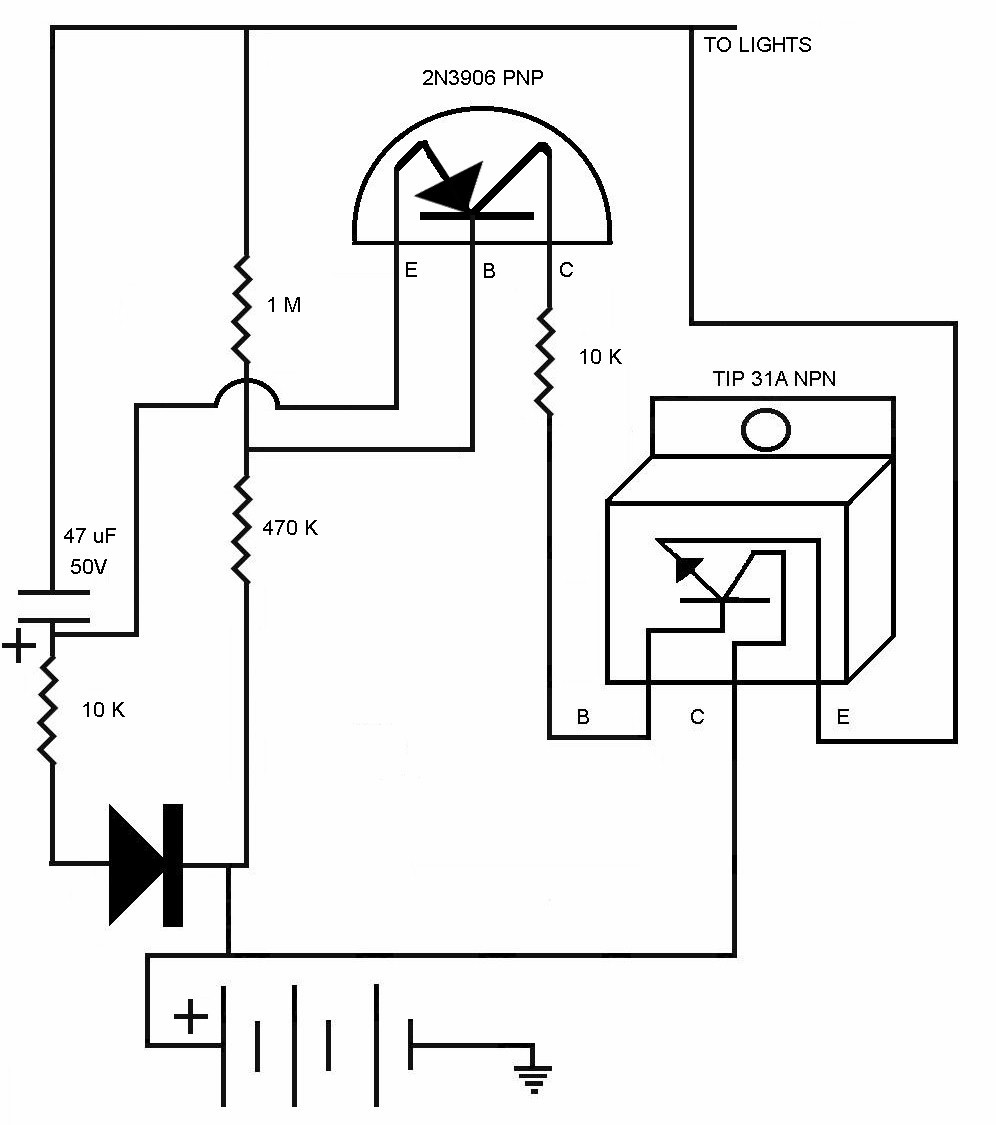
I found some elementary astable flip-flop circuits on the Internet and modified
them to better do what I thought should happen. Without going into too much
detail, an astable flip-flop is a circuit that automatically switches back and
forth between on and off. There is a capacitor in the circuit that controls the
flash rate as it charges and discharges. Through manipulation of the values of
the charging resistors this flash rate can be controlled. I also added a diode
in series with the charging resistor. This slows down the discharge time of the
capacitor and causes more on time per cycle.
Alas, even my discrete component flasher circuit was effected by the RF of the
buzz coils. I decided that I needed a filter circuit. I just hung a couple of
resistors and capacitors to ground, and that did the trick. I also hooked a
beeper that I got at Radio Shack to a couple of diodes. This gives me an audible
warning that my lights are flashing. So far I haven't left them on since I
installed this. For a power supply I use three 9V transistor batteries wired in
series. After loss through the system, that puts about 15V to the lights.
More than the 12V they require, but not enough to cause trouble. You could run
this circuit off of a 12V battery, but the LED's would not put out full brightness.
I experimented with different power supplies, including running the thing off of
the magneto. Without a regulator the voltage kept building and building until it
was around 50V at which point my circuit blew up. When this happened I replaced
the 2N3904 transistor shown in the picture with the more robust TIP31A. I think I
will eventually get a charger and some NiMH batteries, but the 9V alkalines that
I am using are lasting a long long time.

This shows the LED glued into the reflector. I mounted it so that it shines "up". This shows the front light "on".
This is showing the rear light mounted to the underside of the trunk.
Here is the rear light "on"