
by Tom Carnegie-October 2009
Introduction:
Most of my readers should be fairly familiar with the operation
of the model T Ford ignition system. The purpose of this article is to give an in-depth look at the system - not to draw any
conclusions necessarily, but rather to just show what is going
on. I will show some oscilloscope traces of what I've observed. I will try not to be "technical", but because of the nature of the situation some "technicality" is inevitable. I will
not spend a lot of time defining terms, as that would make this
article much longer than I want it to be.
AC operation: The model T magneto puts out a form of alternating current. Below is a graph of a magneto powering a
model T coil. The points on the coil were shorted out.
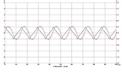
The speed of the magneto was 500 rpm. The voltage is the spiky waveform and the current is the smooth waveform. The voltage is about ten peak volts and the current is about four amps. Most ac voltmeters show rms voltage. Rms voltage is equal to the dc voltage value that would produce the same amount of heat as the ac voltage. For the model T magneto waveform the rms voltage is about 1/2 of the peak voltage.
A word about scope traces. These graphs are just an approximation of the actual situation. Voltage, which is also known as electromotive force (emf), tension, electrical pressure and potential, is not directly measurable. The only way to look at voltage is to sample the effects of the potential across a resistor and then measure the current. All voltmeters work in this manner. Sometimes a mechanical analogy will help a person to understand an electrical situation. Mechanical pressure gSepes work in the same manner as a voltage gSepe. For example, a tire gSepe measures the distention of a diaphragm of known resistance. Just as it is impossible to read tire pressure without using a little bit of the pressure within, it is impossible to measure voltage without using up a bit of it. The voltage waveform on the T magneto can be skewed by a number of things. Any load on the mag skews the waveform. For example, a lightbulb, or some such resistive load will apply drag to the magnetic field created by theflywheel magnets. This torque will pull the magnetic field backwards. For example, if you are running on mag and have mag powered headlights, your ignition timing is going to be retarded by at least as much as the load of the headlights is skewing the voltage waveform.
Below is the current and voltage waveform taken through the same coil as before. This time the magneto is turning 1000 rpm.
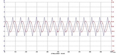
The voltage is now about 20 peak volts. The current, however is still at about four amps. The current essentially stays the same because as a load, the model T coil is mostly reactive. This means that as the magneto tries to put current into the T coil, the T coil tries to put current back into the mag. The faster the mag tries to put the current in, the more the coil resists and a sort of equilibrium is reached.
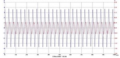
This graph shows the action at 2000 rpm.
If the T coil were a perfect inductor with a perfectly reactive circuit, it would shove exactly as much current back into the mag as
the mag shoved into it. Alas, nothing is perfect. The circuit has some resistance so it loses a little there. This is called "copper loss".
The coil itself has in addition to copper loss some magnetic inefficiencies. These are mostly in the form of eddy currents and hysteresis. Eddy currents are currents imparted to the magnetic core. This current is not used and therefore wasted. Hysteresis is another word for backlash. In this case it is magnetic backlash. The alternating current magnetizes the core alternately north, then south and so on. When the field switches polarity there is a little lag because the core sort of wants to keep its polarity the way it was. The combined magnetic losses are called "iron losses".
Our main point of interest in regard to the operation of the model T coil on magneto is hysteresis. Not only magnetic hysteresis, but mechanical
hysteresis. Mechanical hysteresis is mainly from two sources, the inertia of the points and the point drop on the upper point.
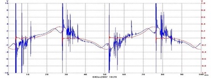
Above is a graph of a coil firing as if on a hand-cranked coil tester. The volt and amp scale are both from -10 to 10. There are 8 cycles per revolution on a T mag. There are 60 seconds in a minute and 1000 ms in a second, so if we take the time of a complete cycle (about 50ms in the above graph) and multiply its reciprocal by 60000/8 we will arrive at the rpm. The above graph was taken at about 150 rpm. At this speed it takes about 14ms for the coil to fire from the zero point on the amp waveform. The coil fires just slightly on the downward side of the amp peak. I believe this is a result of mechanical hysteresis. Operating a coil on a steady AC voltage is a common way to test and set up a coil. In reality, the model T coil never encounters this situation. The reason for this is the timer. In part three I will show the timer's effect on coil timing.