A Poor Man's Dynamometer
by Tom Carnegie-March 2005
Most Montana 500 people have a pet way that they test their model T's to see if their tweaks have improved performance. Some may involve driving up a certain hill. Others may involve driving flat-out on a certain stretch of road. Among the problems I have with these methods is the inability to control outside variables that may effect the results of these tests. The chief offender is wind. Wind has a huge effect on the performance of a model T near its top end. Other factors that can effect results are air temperature, humidity and barometric pressure. Even how you are driving or traffic can have effects. It is also hard to change things in real time and see instant results. The answer to all this is a dynamometer, of course. Dynamometers for large horsepower motors are very expensive. A model T only puts out around 20 horsepower, so there is a fairly easy way to make a suitable dyno dedicated to testing T motors. What a person needs is a hydraulic pump coupled to the back of a T motor. On my poor man's dyno, I used a 1.53 cubic inch pump. By taking the pump size in cubic inches "C" multiplying it by the RPMs, "R" and dividing by 231, you get gallons per minute "G". CR/231=G. G times pressure "P" in pounds per square inch divided by 1628.3 equals horsepower "H". GP/1628.3=H. H times 5252 divided by RPMs, equals torque. "T" H5252/R=T. It is very easy to set up a spreadsheet in Excel or some spreadsheet program to do the math for you on this.
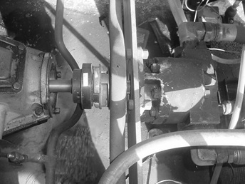
This is a shot of the T motor coupled to the pump. The coupler has a piece of reflective tape for use with the optical tachometer.
There are also SAE formulas for compensating for various ambient weather conditions that can be integrated into this spreadsheet. If any one needs help with a spreadsheet to do this, let me know and I'll get one going for you. Once you have the pump coupled to the motor, you will need a valve to restrict the flow of hydraulic fluid.
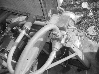
For water and oil circulation I used impeller pumps. I plumbed the water lines with half inch flexible hose. The radiator is an old car radiator cooled with a box fan.
My homemade dyno uses a 15 gallon barrel as a tank and the fluid is pumped from the tank, past the pressure gSepe, through the restrictor valve and back to the tank. Turning off the valve restricts the flow of oil, and puts a load on the motor.
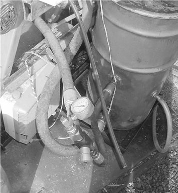
This shows the oil storage tank, the restrictor valve and the oil cooling fan. I ran the oil through a small radiator to help cool it too.
When you are testing a motor, most of the power is being dissipated as heat into the oil. It doesn't take very long before the oil is too hot for the pump to pump safely. I have a separate circuit on my dyno to pump the oil through a cooler so that I can test motors for a longer stretch at a time. I also have a radiator and pump to pump cooling water through the motor being tested. In addition to measuring the hydraulic oil pressure, you will need to measure the RPMs of the motor also. One way to do this would be to install a distributor and hook a tachometer up to it. The way I do it is with a handheld digital optical tach. You put a piece of reflectie tape on a rotating part and shine the tach onto it. It then tells you how many revs are happening. Pretty slick, and it will work with timer and coils. That is really all there is to it. Depending on your engineering skills, this should be fairly easy for most people to do. At today's prices I think a person can build one of these for under $1000.00 dollars.
(end of article)