
by Tom Carnegie-January 2008
Many of the readers of this article have likely charged their
model T magnets in one way or another. One common way
is to use the magneto field coil to charge the entire magnet
set at once. This can be done with the magnets in the car.
If you desire the ability to charge the flywheel magnets individually
it can be accomplished with parts salvaged or purchased cheaply.
What you need:
Transformer - the one I used was from an old television
set. I think a microwave oven transformer would work
well. They are easily obtained. The bigger, the better.
Bridge rectifier - buy the highest amperage rated one for at least 120
volts that you can get.
Radio Shack Part no. 276-1181 is 6 amp 200 volt unit, which should be adequate,
although bigger and better ones are available on E-Bay.
5 amp fuse and holder.
Switch,
Power, cord
Hot plate.
There are essentially three parts to this set-up. One: the
electromagnet, Two: the rectifier and Three: the current limiter. We will use
the 110-volt primary windings of the transformer to make our magnet. The 110-volt
primary windings are the ones that the power cable originally attached to. A
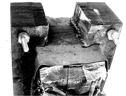
transformer does not make a good electromagnet without being modified. You will
need to cut a notch out of the transformer to make a north and south pole.
(see picture) I just hacked it out with a hacksaw. The electromagnet needs to
have a steady north and south pole. If the electromagnet were powered by house
current the north and south poles. would be alternating sixty times per second.
To make the poles constant requires direct current. This is done with a rectifier.
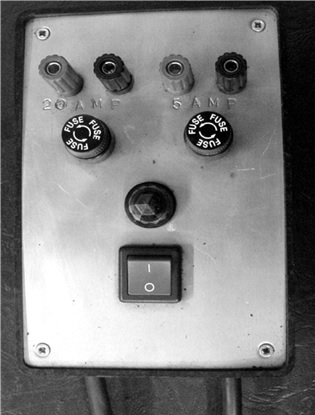
On the schematic there is a box drawn around the rectifier section of the circuit.
I mounted my rectifier into a hobby box from Radio Shack. (see picture) My
rectifier is actually two rectifiers in one. For this project we only need one.
The DC coming out of this circuit is substantial, so care should be taken when
working around it. It is around 90 volts and the amperage is limited by the size
of the rectifier and fuse.
The amount of magnetism produced by an electromagnet
is a function of current and the number of turns of wire. This is known as
"amp-turns". To a certain degree it is also affected by how well the wire is
wound onto the iron transformer core. This is called the "Q" factor. "Q" stands
for quality. There are many turns of wire in a transformer such as we are using
for our charger. This is good and bad. It is good because more turns mean more
magnetism. It is bad because it is harder to shove current through small wire and
current is half of the amp-turn picture.
As it turns out we have plenty of
current to fill our transformer core. At a certain current level the transformer
core will become saturated with magnetism. When the current reaches this level,
any added current will be wasted and dissipated as heat. A direct connection from
the rectifier to the electromagnet would likely exceed this current level so the
current is passed through a hot plate, or some other resistive load to limit the
current through the windings of the transformer. The hot plate I used was about
1000 watts.
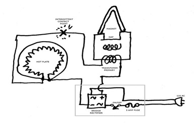
The "X" on the schematic denotes a break point in the circuit where the DC to the transformer is made and broken. To charge a magnet does not require a steady shot of current. Brief pulses are better as they will tend to hammer the magnetic "domains" into alignment. A momentary contact switch would work well for this, although I just sparked the two wires together. Traditionally if a model T magnet is able to pick up a cast iron T piston which weighs about two pounds, it is said to be sufficiently charged. A typical model T magnet will do this if it has around 650 gauss of magnetism. This varies some from magnet to magnet. This charger setup should charge a T magnet into the 800 or 900 gauss range. I will present a separate article on how to make a gauss meter.