
by Tom Carnegie-April 2010
In parts one and two I described the operation of the coil on D.C. and A.C. Part three shows what happens when the timer is thrown into the circuit. Operating a coil on a steady AC voltage is a common way to test and set up a coil. In reality, the model T coil never encounters this situation. The timer just takes a little chunk out of the voltage waveform, and applies that chunk to the coil. Where the timer "turns on" in relation to the potential available will determine when the spark will occur.
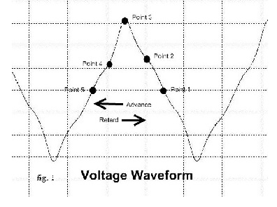
In normal operation, the flywheel spins around to produce voltage. When the timer closes, current will begin to flow in the coil. Where the timer closes the circuit in relation to the voltage waveform has quite an effect on how the coil will respond. I will show some graphs of the subsequent amp waveforms that result from the timer closing the circuit at various times. When the timer closes at "point 1" of the graph shown in fig. 1 above, it may come as close to duplicating a hand-cranked coil tester as is possible with a timer. The timer is closing right at the "null" or zero point of the waveform.
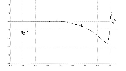
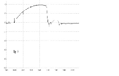
The graph shown in fig. 2 corresponds to the timer closing at "point 1" on the voltage graph (fig. 1).
In this and the following examples the flywheel is turning about 1100 rpm. At this speed each ms (x axis) is about
6.5 degrees. The timer closes at 7.1ms, which is near the null point of the voltage waveform. The amperage then
builds to about negative 5 amps, at which point the coil fires at about 8.9ms. In this example we’ll say that
8.9ms occurs 18.5 degrees before TDC (which is more or less, but not exactly correct). You will notice that the
current rises to well over 5 amps, yet as shown above, the current barely rises above 4 amps when powered by a
hand-cranked coil tester. This is because when the current is triggered by a timer, the coil doesn't "know"
that it is being powered by AC. All the coil "sees" is a rising voltage. Until the voltage switches polarity
(which it doesn’t in this situation) the coil is effectively being operated on DC. The timer in this situation
is in fact operating as a mechanical rectifier.
Time to fire: 1.8ms which equals 11.5 degrees.
Absolute fire time: 18.5 degrees BTDC
Timer advance from null point: 0 degrees
Spark advance from starting point: 0 degrees
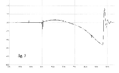
The graph shown in fig. 3 corresponds to the timer closing at "point 2" on the voltage graph shown in fig. 1.
The timer has been advanced about 5 degrees and closes at about 6.3ms, which is about half way between the null point and
the positive peak of the voltage waveform. The amperage builds to about 1 amp, which is not enough to fire the coil.
The amperage then begins to build negative and the coil fires when the amperage reaches about negative 5 amps at about 9.1ms.
9.1ms occurs 17.2 degrees BTDC . The timer is advanced 5 degrees from the previous example, yet the spark has retarded 1.3 degrees.
This is because the coil has to "undo" what it started to do. That is, the coil began to build positive, but ultimately fired negative,
so the time spent building positive voltage was wasted.
Time to fire: 2.8 ms which equals 18 degrees.
Absolute fire time: 17.2 degrees BTDC
Timer advance from starting point: 5 degrees
Spark advance from starting point: -1.3 degrees
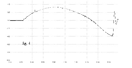
The graph shown in fig. 4 corresponds to the timer closing near "point 3" on the voltage graph shown in fig. 1.
The timer has been advanced 12.2 degrees and closes at 5.2ms. The amperage builds to a little over 3 amps, which is not
enough to fire the coil. The amperage then begins to build negative and the coil fires when the amperage reaches about
negative 4 amps at about 9.2ms. 9.2ms occurs 16.5 degrees BTDC . The timer is advanced 12.2 degrees from the first
example, yet the spark is retarded 2 degrees. This is the point of maximum disparity between timer advance and spark retard.
Sometimes with the timer set at this point there will not be enough power in the mag to fire the coil from either the negative
or the positive amp pulse. This is especially true if the mag is sub-par or the coils are poorly adjusted.
Time to fire: 4 ms, which equals 26 degrees.
Absolute fire time: 16.5 degrees BTDC
Timer advance from starting point: 12.2 degrees
Spark advance from starting point: -2 degrees
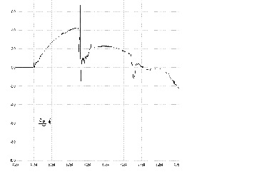
The graph in fig. 5 shows the timer advanced about 1 degree from the graph in fig. 4. The timer has been
advanced 13.5 degrees and closes at 5ms, which is right before the positive peak of the voltage waveform. The amperage
builds to about 4 amps, which is just enough to fire the coil at 7ms. 7ms occurs 32.75 degrees BTDC . The timer is
advanced 13.5 degrees from the first example and the spark is advanced 12.2 degrees. 1 degree of timer advance resulted
in 13.2 degrees of spark advance. The coil is now firing on the positive pulse, but the spark has not quite cSepht up
to the timer.
Time to fire: 2 ms, which equals 12.8 degrees.
Absolute fire time: 30.7 degrees BTDC
Timer advance from starting point: 13.5 degrees
Spark advance from starting point: 12.2 degrees
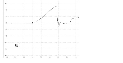
The graph shown in fig. 6 corresponds to the timer closing at "point 4" on the voltage graph (fig. 1). The timer
has been advanced 15.5 degrees and closes at 4.7ms, which is between the positive peak and "null point" of the voltage waveform.
The amperage builds to about 4 amps which fires the coil at about 6ms. The timer is advanced 2 degrees from the previous example
and the spark has advanced 5 degrees. Of all examples presented in this article, this one has the fastest time to fire. This
is because when the timer closes the circuit, there is a large potential available. When the timer is in this position the
spark has advanced more than the timer.
Time to fire: 1.3 ms, which equals 8.3 degrees.
Absolute fire time: 37 degrees BTDC
Timer advance from starting point: 15.5 degrees
Spark advance from starting point: 18.5 degrees
The graph in fig. 7 corresponds to the timer closing at "point 6" on the voltage graph (fig 1.). The timer
has been advanced 22.5 degrees and closes at 3.6 ms, which is near the null point of the voltage waveform. The amperage
builds to about 6 amps, which fires the coil at 5.4ms. This is the same situation as the first graph in this series (fig. 2),
except the voltage polarity is reversed.
Time to fire: 1.8ms, which equals 11.5 degrees.
Absolute fire time: 41 degrees BTDC
Timer advance from starting point: 22.5 degrees
Spark advance from starting point: 22.5 degrees