A Poor Man's Balancer
by Tom Carnegie
One of the major tricks to making an engine run fast is to make it run smooth. With a Model T, this is a difficult task for several reasons. First of all, a four-cylinder engine without balance shafts will never run in true balance. This is because when the crankshaft is half way down (90 degrees off of top dead center) the pistons are more than half way down. The pistons actually move faster on the top half of their travel than on the bottom half. This may be hard for some people to visualize, but it is the case. One thing that sometimes helps illustrate this is to imagine an engine with its rod hanging loose. If you were to pull the piston exactly half way down the bore, and continue to let the rod hang, the crank hole in the rod would exactly line up with the main line. If you would turn the crank to its halfway point, it would be 90 degrees from top dead center. Now, if you were to hook the rod to the crank, without turning the crank, you can see that you would have to pull the piston down slightly to get it to hook up, as you swing the rod toward the crank. Having said all of that, there is a couple that occurs twice per revolution that can't be relieved under normal circumstances. It can be mitigated though, by using the lightest rods and pistons that you can find. A couple is a rocking motion. A good example of a couple is two kids on a swing set. When one is forward, the other is back and vice versa. The force put onto the upper bar of the swing set is a "couple". Other reasons for the balancing difficulty of a T engine have to do with the transmission. There are many parts like drums and clutches that move around, making a true balance all but impossible. Still, the closer you can get everything else, the better. This article will tell how to build a very accurate dynamic balancer for almost no money.
Balance, do!
For the assembly of this machine, you will need the following items:
- 3 - junk T engine blocks
- 4 - used T generator bearings
- 2 - Pieces of 2" angle iron 3 1/2 inches long each
- 5 - 3/8" X 1" NF bolts
- 8 - 3/8" flat washers
- 4 - 3/8" lock washers
- 7 - 3/8" NF nuts
- 2 - 7/16 X 3/4" NC bolts
- 1 - No. 10 - 32 X 3/4" machine screw
- 1 - old 28-9 Model A or Model T bumper bar
- 1 - 3-lb. coffee can with lid.
- 1 - 3/8" rod 7-1/2" long
- 1 - circle of tin 5" in diameter
- 1 - circle of tin 3" in diameter
- 1 - set of distributor points
- 1 - ignition coil and coil wire
- 1 - condenser
- 1 - timing light
- 1 - battery to operate timing light and coil
- 1 - 1" by 8" long piece of strap iron
- 1 - 1/4" diameter rubber bumper
- 1 - 3/8-drive variable speed drill motor
- 1 - an old starter or generator case
- 1 - 1/4" ball bearing
- 1 - dial indicator
Scallop both pieces of angle iron as per the illustration. (fig 1.)
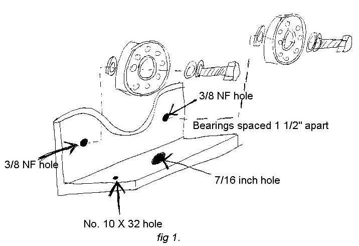
Drill two holes into each piece, for the bearings, and tap to 3/8" NF. Drill a hole into the center of the bottom of the piece of angle iron large enough for a 7/16" bolt. Into one of the two pieces, drill and tap a number 10 X 32 hole into the bottom front of the angle iron, as per the illustration. Bolt the bearings onto the angle iron pieces. (See pic. 2.)
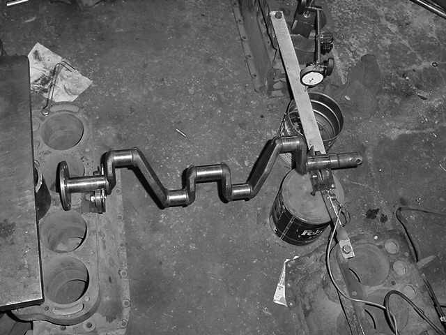
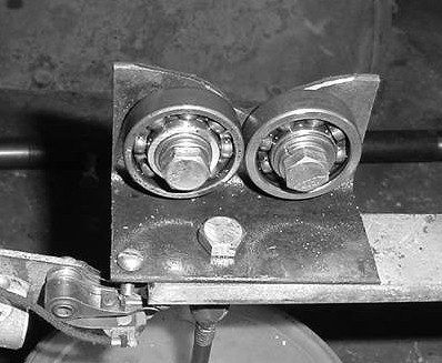
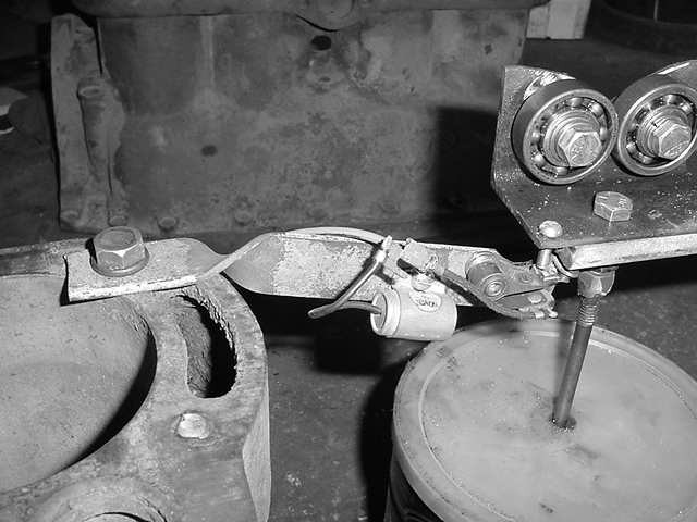
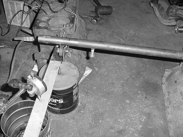
The bearings need to be very clean, and must spin freely. Put a drop of oil into each bearing. Cut the bumper into a section 20" long, and drill a 7/16" hole 3/4 of an inch from each end. Bolt one roller assembly loosely to one of the T blocks. Bolt the bumper section snugly to another of the T blocks. Bolt the other roller to the other end of the bumper, loosely. Space the rollers out so that a Model T crankshaft will roll on the first and third main. (As per pic. 1.) Adjust the roller assemblies so that they are running true on the crank main, and then tighten them. Spin the crank clockwise, looking from the spring end. If the crankshaft "walks" left or right, move one of the blocks forward or back and try again. Carefully adjust the crankshaft until it spins freely, and just creeps to the left as it is rotated clockwise looking at the end that is sitting on the spring (the bumper piece). Put some grease on a 1/4" ball bearing and stick it into the end of the crankshaft. Butt the ball up against the generator housing that you have sitting on the block. (See pic. 1) Place something heavy onto the generator housing to keep it in place. It is also handy to thread a bolt into the block for the generator case to butt up against to keep it from moving. Most unbalanced T cranks I' v e tried will come to rest in heavy-part-down position if you set them on the rollers at this point. The next thing to build is the dashpot. What this does is dampen the action of the spring somewhat. It consists of a disk on a rod in a can of oil. (See fig 2)
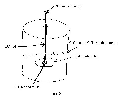
You can make a couple of different sized disks to change the sensitivity of the balancer. The next thing to do is to make the point setup. Take a piece of 1" strap, and twist it 90 degrees near the end. (See pic. 3)
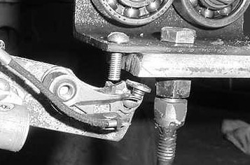
Drill a 7/16" hole near the end, to bolt the assembly to the block. Mount the points and condenser on in the manner of pic. 4. The machine screw needs to be adjusted so it is a few thousandths of an inch from the points when the item to be balanced (henceforth called the rotor) is in place . Wire a coil and battery to the points, and attach your timing light to the coil wire in the correct manner. Let the coil wire spark to ground in some convenient place. Don't apply electricity to the coil until you are ready to begin balancing, as leaving the electricity applied to the coil could cause it to overheat.
A Balancing Act
In order to balance the rotor, it must be spun. The way I do this is with a variable speed electric drill. Place a pointed piece of rubber into the drill, and the rotor can be spun by placing the rubber into the center on the end. Now, the cool thing about this balancer is that it can balance in two planes. I will explain what that means. Some people refer to dynamic and static balance. Please refer to pic. 5.
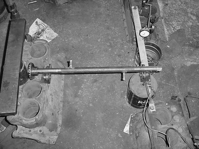
That is an axle shaft with a bolt welded onto it. If you were to gently spin the axle, it would always come to rest with the bolt down, as it is in the picture. Now, look at the axle in pic. 6. It has another bolt at the other end of the shaft welded just opposite the first bolt. However you turn this shaft, it will stay in that position. This is what some folks refer to as static balance. I do not like this term, as any static shaft has reached equilibrium, and therefore by definition is in balance. In order to be out of balance, the shaft must be turning. I prefer to use the term "balanced in one plane" or "balanced in two planes" in exchange for the terms "static" and "dynamic" balance. It is easy to see that if you consider the axle in pic. 6 as one plane its entire length, that it is in balance. If you divide the axle into two planes, a right plane and a left, splitting the axle figuratively in the middle, it is easy to see that each plane is quite out of balance, just as the axle in pic. 5 was. Our quest is to get our rotor balanced in two planes. To accomplish this, we balance it one side at a time. The rotor we are talking about in this case, is the crankshaft, which should be balanced with the pulley and crank gear on it. As I mentioned earlier, when you place the rotor into the machine, it will probably come to rest in the same place every time you spin it. In fact, it may be so out of balance, that even at a moderate speed of rotation, it will try to jump out of the rollers. What I do, is to get it into reasonable balance in one plane first. Note the heavy spot. It will likely be two of the four rod throws. Grind or drill away some metal on the heavy spots, and try again. At a point in time, the rotor should stay at any position you put it. You are now ready to begin balancing in two planes. Use the large dashpot disk at first. As the rotor comes into better balance, substitute the small disk for greater sensitivity. On the end of the rotor make three marks as per fig 3.
Place a dial indicator on top of the spring as in pic. 1. Spin the rotor, and adjust the point screw so that the timing light just flashes at the point of maximum imbalance. This point can be noted on the dial indicator. As you spin the rotor, it will be relatively smooth, then will become rough, and then will smooth out again. There is no need to spin it above the speed at which it smoothes out. Spin the rotor up, and as it slows, watch the flashing of the timing light. One of the marks should appear to stand still 90 degrees to the right of top (1. in fig 4) then, as the rotor slows, the mark will appear to rotate anti-clockwise until it is at the top when the point of maximum vibration is reached (2. in fig 4). As the rotor continues to slow, the mark will appear to rotate 90 more degrees to the left as the rotor slows to below the imbalance speed (3. in fig 4). Where the mark appeared at the moment of maximum imbalance is the light spot. That means that you need to take off material opposite this and in the plane in which you are working. There are two rod throws in each plane, and normally one of these will be down when the balance mark is up. If it is the rod throw closest the end, you will \have to take off less material than if it is the other, as it is farther out on the plane we are balancing at this time. After a few times, turn the rotor end for end and balance the other plane for a while. As you get the rotor closer and closer to being in balance, you may encounter the situation where the rod throws are parallel to the ground. When this happens, you must drill the flange or the timing gear or the pulley. When you get to the point that the dial indicator is only moving one or two thousandths of an inch at the roughest spot, then you are probably close enough. The machine I built was admittedly a little crude. With a little adapting, a permanent machine could be made to do a whole host of balancing projects. I built mine out of old T blocks because they were handy, and quick. It was also an experiment, but it worked well enough to give me incentive to refine it, and perhaps make it more permanent.
A question of balance
They say the proof is in the pudding. When I got to the point that my rotor was only out of balance a few thousandths on the indicator, I decided to see just how good it was on a commercial machine. Jack Bunton of Vintage Engine Machine, has a Stewart-Warner precision balancing machine, which he kindly let me use to check my work. The scale on his machine goes from 1 to 10. Anything under 1 is considered acceptable. My crank registered just two tenths. This is the level of balance that you would expect on high revving racecar motors. The pudding is quite good indeed, and inexpensive too.