By Tom Carnegie-November 2005
In order to better understand the function of a model T timer
it is useful to look at its operation with an oscilloscope. A
good deal of money can be spent on an oscilloscope, but
there are reasonable alternatives. With a bit of poking
around, one can find circuits and software to convert your
existing PC into a decent oscilloscope. I chose instead to
buy a commercial unit that plugs into the parallel port of the
computer. The unit I got was manufactured by Pico and was
less than $100.00 including the software at the time of this
writing. The model number was ADC-10. It has some limitations
as an oscilloscope, but is quite ideal to test the
switching properties of a timer.
Job Description:
The job of the model T timer is to ground the coil for each
cylinder at such a time as to allow the plug to fire and ignite
the fuel in the combustion chamber. The model T timer is
essentially a single-pole four-throw switch. In a perfect
world a switch would either be on, or off. In the real world
it never happens quite this way.
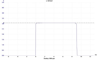
The perfect model T timer would not only turn perfectly on, then off, it would do it at exactly 90-degree intervals over the range of rpm's that the engine operated. The previous picture shows a nearly ideal waveform for a Model T timer. It is from a Duntley timer, turning at 1000 rpms. To clarify, in this article in regard to degrees or speed, unless otherwise stated, I will refer to timer rotation as opposed to crankshaft rotation. The timer rotates at 1/2 crankshaft speed, therefore all speeds and degree figures for the crankshaft are twice that of the timer. The timer also needs to dwell in the "on" position for a certain amount of time. This dwell period is not too critical as long as it is adequate. I will explain better later on.
Solid Ground
There are basically two ways in which mechanical (nonelectronic)
timers function. Most timers are what I call the "wiper" kind.
The way they operate is to have a wiping contact that is connected
to the camshaft. This wiper then contacts a commutator that is
wired to the coil box. In the second kind, the commutator is
self-grounding and the cam is used as a triggering device.
Triggered timers have some advantages over wiper timers, but
aren't allowed on the Montana 500. Wiper timers have at least
two disadvantages. One is that the wiper is scooting across the
commutator contact. It never really makes a solid connection, but
rather arcs and sparks its way across the contact surface.
Two is that the wiper must get its ground through the camshaft,
which is theoretically rotating on a film of oil. Some folks
have said that there may be an advantage to using metal timing
gears because the cam can then ground through the gears to the crank.
That may be true, but the gear teeth should have an oil film on
them and the crankshaft should also be riding on oil! Some other
folks say that the timer brush (rotates) gets its ground through
the tin shield that is used to hold the felt in place. Even so,
it is still a wiping situation between the brush and the shield.
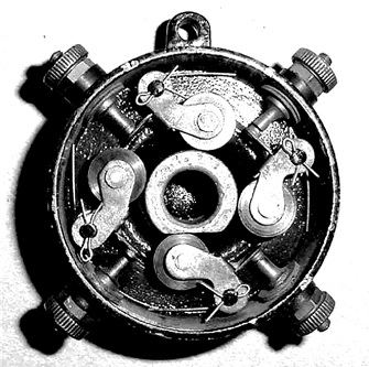
The above photograph shows a Duntley timer. The contacts ground through the case rather than through the camshaft.
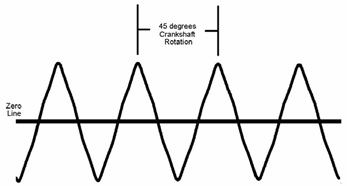
Pictured above is a waveform from a Model T magneto. The highpoints of the waveform occur every 22.5 degrees of crankshaft rotation. Whether the highpoint points up or down from the center (zero line) is not important, either pulse will energize the coil. The flywheel is indexed to the crankshaft in such a fashion as to cause the high point to occur at certain exact times. The useful times these pulses occur listed from retarded to advanced are: 4 degrees after TDC, 18.5 degrees BTDC and 41 degrees BTDC. Ron Patterson and Steve Coniff have written an article that goes into more detail on this subject. It can be found on the Internet at http://www.mtfca.com/encyclo/Ignition.pdf. It should be noted that these timing figures apply only to when the car is running on “magâ€. When running on battery, the timing is continuously variable throughout the aforementioned range. Chiefly because six volts is not enough to properly energize a Model T coil, model T's don't run well on battery. As such this article will be confined to issues dealing with magneto operation. For every revolution of the timer there are thirty-two pulses from the magneto. Of the thirty-two pulses, twelve are useful, three for each cylinder. An ideally functioning timer would operate as a selector for these useful pulses. Even a less than ideally operating timer could be fairly adequate.
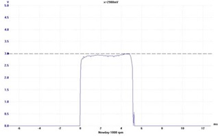
Above is the waveform of a well functioning Newday timer. The dotted line shows the maximum that is possible for the timer to let through. Although the waveform is slightly ragged and doesn't come up to the maximum line, it is likely functionally equivalent to the Duntley timer shown earlier. As mentioned earlier, a timer must turn on then stay on (dwell) for a certain amount of time. How long it dwells is not critical as long as at least one pulse of the magneto fires the coil. During a dwell phase, the coil could fire several times. The only important one is the first one. All subsequent firings during this particular dwell phase are redundant. So what is the significance of all this? The timer needs to turn on cleanly at the central timing point, (see side bar), which corresponds to the zero point of AC voltage generated by the magneto. If the timer doesn't turn on cleanly, the timing will be affected.
The timing is fairly stable at the useful points mentioned in the text. What exactly happens to the timing as the spark lever is advanced? Starting at a certain point, which I will call the central point, as you begin to advance the spark lever, the timing immediately begins to retard. This retardation is logarithmic, so it is nearly imperceptible at first. As you continue to advance the lever, the retarding will accelerate in relation to the advancing of the lever. At a point in time as you continue to advance the lever, the spark will become unstable, then jump ahead in timing. As you continue to advance the lever the spark will now advance in a logarithmic fashion, fast at first, then slower and slower until it reaches the new central point, which is 22.5 degrees advanced from the old central point. As you continue to advance the lever, the timing will begin to retard and the cycle starts over again
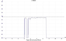
The graph below shows the results of a flapper timer with a weak spring. Depending on where your spark lever is set, this could have a minor, or significant impact on the spark function.