Download/PDF
Measurements of the Magnetic and Oil Drag in the Model T Transmission
Larry Azevedo, 2022
Abstract
The power required to turn a stock Model T magneto has been measured as a function of magnet / field coil spacing at various RPM’s. It is found that the power required to turn the magnets past the field coil can be a large fraction of one horsepower at close gaps of the magnets and field coils. This power is primarily due to eddy current losses in the field coil poles. Additionally, the power required to turn the flywheel/magnet combination has been measured with various quantities of oil as a function of RPM. It is found that oil levels approaching the 4 qt level require nearly one horsepower at high RPM’s.
Having gotten ‘hooked’ on participating in the Montana 500 Endurance Run I became interested in understanding how much power is robbed from the Model T engine due to the magneto and oil drag. I decided to build a ‘mini dyno’ to directly measure the power it takes to turn the flywheel/magneto assembly in the engine oil. The principle of the dyno is quite simple and the same as regular ‘big dynos’. As the flywheel/magnet combination turns in the pan, a torque is applied from friction (due to bearings, air resistance and the presence of oil) and the power that is required to pass the magnets across the magneto iron poles. The torque tends to ‘twist’ the engine assembly in the direction of rotation. By suspending the engine pan on bearings along the axis of rotation one should be able to measure the induced torque and thus the horsepower. The torque causing the engine pan to twist can be measured by balancing a known mass at a given distance from pan’s center of rotation in a horizontal position. Knowledge of torque at a given RPM then allows the determination of horsepower.
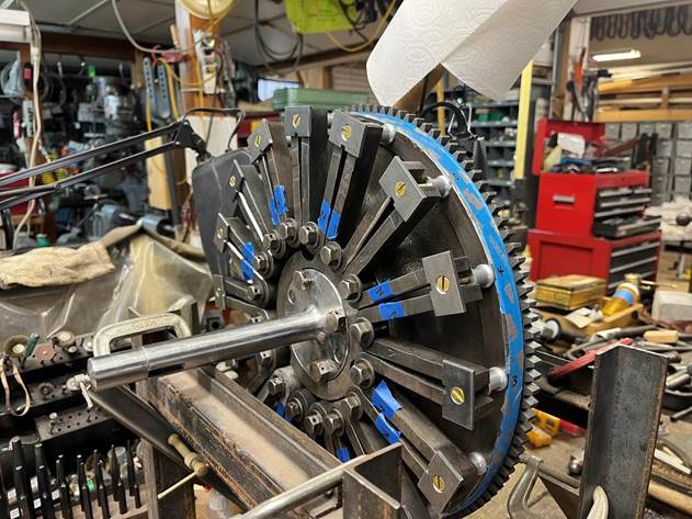
The design was as follows: A Model T 4 dip pan was suspended on a couple of large ball bearings which were centered down the crankshaft line. Using an old Model T driveshaft, a main line drive shaft was installed in the pan to allow installation of a flywheel/magnetic assembly. A crankshaft rear flange was welded to the main drive shaft and turned true on a lathe. An old T engine block was vertically cut in front of the rear cylinder, bolted to the pan and served as the mount for a rebuilt magneto ring (late model w/ gap for starter installation). A 26-27 hogshead was used for oil drag measurements. The flywheel was mounted with recharged magnets and carefully balanced. 16 magnets were selected with individual masses within 1 gram of one another. The overall static balance of the flywheel was within a few grams at the outer rim of the flywheel. Balancing was done by placing the flywheel assembly on leveled knife edges using opposing transmission shafts. The flywheel assembly, on the knife edges, was balanced and sensitive to 2 or 3 grams of weight (3/8” flat washer) added to the rim. At the highest RPM measured (~2000 RPM) the system ran smoothly with very small vibrations.
It was decided to just use the flywheel/magnet assembly without the associated drums. For the oil drag measurements only the drag of the flywheel and magnets was measured in various quantities of oil. The assumption was that the transmission drums, since they do not directly contact the oil level in the pan, have a small contribution to oil drag.
Setup: A ¾ HP two speed electric motor was installed on the front of the dyno with a V belt pulley and a stepped v belt pulley was mounted on the driveshaft. This motor was selected because it’s cheap ($100) and could be used as a backup swamp cooler motor in the future if the dyno turned out to be a bust. The configuration allowed a combination of 8 speeds from 860 to about 2000 revolutions per minute. RPM was measured by a hand held RPM meter with the laser aimed at the rotating shaft which had a reflective sensor attached. Getting the motor up to speed was tricky (triggered a circuit breaker several times!) and it was necessary slip the belt and allow the system to slowly come up to the desired RPM. This was necessary since the ¾ HP motor did not have low speed torque to initially start the dyno without drawing a ton of current and tripping a circuit breaker. The motor was mounted on a pivot and the motor weight was used to maintain belt tension.
Sensitivity: It is important to balance the entire system prior to making a measurement. This was performed by adding counterweights at appropriate locations around the pan so that the pan would balance in a flat position. The pan free rotation was limited by stops so the pan could only rotate a few degrees around the axis of rotation. Initially the sensitivity was measured to determine the smallest torque that could be detected. With the pan balanced the minimum repeatable torque (at zero RPM) was found to be equivalent to a mass of 66 grams on a moment arm 13” from the center of rotation. This corresponds to a minimum detectable torque of 0.157 ft-lbs(torque = 66/454 x 13/12 ft lbs).
This is the dyno shown from the right side of the pan. The driveshaft is supported by two ball bearings inside the pan and a 4th main ball bearing in the back. The blue bar off the side of the pan/hogshead connection is the moment arm in which weights were hung to rebalance the system when a torque caused the system to rotate clockwise from the front. Note the oil on the floor! With the partial engine block open to the front oil really splashed out. It was necessary to build a sheet metal wall in that area to keep the oil under control. Initial measurements were performed without a starter in place. The starter mounting holes were blocked off.
The mini dyno shown from the left side. Note the bearing at the rear which, with another bearing at the front, allows free rotation of the pan/hogshead/flywheel system.
Static balancing the flywheel and magnets on leveled knife edges The horsepower is related to RPM and torque as follows:
𝑅𝑃𝑀 𝑥 𝑇𝑜𝑟𝑞𝑢𝑒
𝑃𝑜𝑤𝑒𝑟=
![]() (1)
(1)
5252
In equation (1) RPM is measured in revolutions per minute and torque in foot-lbs resulting in power in units of horsepower. Using the above measured sensitivity (66 grams at 13”) the minimum detectable horsepower can be calculated using Equation (1). The minimum detectable horsepower is shown below as a function of RPM.
Figure 1
Figure 1 shows the minimum detectable horsepower at various RPM’s. The repeatability of measurements was also measured. Typically, the repeatability for a given measurement was between 5 and 10% of the value measured. This represents the actual accuracy of the power measurement since the uncertainties of the weight, RPM and moment arm measurements are all much smaller than 5%. (the accuracy of the weight measurement was 2% for the worst case, moment arm was 4% worst case and the RPM was accurate to 10 RPM or 1.3% worst case.)
Electrical Power Measurements
The first series of experiments were run with a ‘dry’ system (no oil) with the hogshead cover removed. The power required to turn the magneto at a given RPM was measured. For any power measurement one needs to determine all contributions to the measurement. In this case, there are the following contributions to the measured power:
1. Air resistance (anything rotating in open air)
2. Friction from the bearings (including the 3 bearings supporting the pan structure) and belt friction
3. Electrical power generated from the current supplied by the magneto when connected to a load (𝐼2𝑅 where I is the current flowing through a resistance R)
4. Eddy current losses in the field coil cores and other magnetic drag not attributable to 𝐼2𝑅 losses
The first two terms can be separated from the last two by measuring the total power as a function of magneto spacing as discussed below. Eddy currents result when a changing magnetic field is applied to a conducting material. Electrical currents, due to the changing magnetic field, are induced in the conductor. These currents are lossy and dissipate energy through heating the conductor(the field coil cores). We are also including any other losses from magnetic effects due to the mag coil poles in term #4 above.
The 𝐼2𝑅 contribution can easily be estimated. The typical coil system for a Model T running on magneto draws about 1 – 2 amps into about a few ohms of resistance. This would correspond to approximately 22 𝑥 3 𝑎𝑚𝑝2𝑜ℎ𝑚 = 12 𝑤𝑎𝑡𝑡𝑠. 760 watts is one horsepower so the power generated due to current through the coils would be about 12/760 = 0.016 horsepower which is very small. This assumes all the dissipation through a resistor and no other losses. For all the measurements reported here the magneto post was not connected to a load so the power dissipated from #3 above is zero and all other magnetic and/or electrical losses are incorporated into #4 above.
Figure 2 displays the total measured horsepower vs. magneto gap at 735 RPM.
Figure 2
Note that the power is leveling off for a magneto spacing greater than about 0.2 inches. This value, approximately 0.055 HP, is the resulting air resistance and friction (contributions #1 and #2 above) at 735 RPM. Subtracting this value from the rest of the data at closer magneto gaps is then a direct measure of the power it takes to turn the flywheel due to eddy currents and other magnetic losses. Note that since the magneto is operating without a load there is no current flowing and therefore no loss due to #3 above. The open circuit rms voltage of the magneto was also measured at this RPM and is shown below as a function of mag spacing.
Figure 3
As expected, the voltage rapidly increases with decreasing magneto spacing. Note that the Ford Manual specifies that the magneto spacing be set at 0.03 inches. This closer spacing helped to account for the eventual increase in spacing due to wear in the rear main bearing thrust surfaces.
The next graph shows the rms magneto voltage (open circuit) vs RPM at a magneto gap of 0.049 inches. Note that the voltage is linear with an intercept of zero which is expected to be the case.
The eddy currents and other magnetic losses will continue to be more lossy at higher RPM’s.
Figure 4
In Figure 5, below, the background (air resistance and bearing friction) has been subtracted from the data in Figure 2:
Figure 5
Since we expect the eddy current loss to be linear with RPM we can then extrapolate the data in Figure 5 and predict the eddy current power loss at three magneto gaps as a function of RPM.
Figure 6 (mag spacings of 0.049, 0.085 and 0.125 in)
Word of caution! This is extrapolated data from the original which has uncertainties not shown here and should only be used as a guide. Given that, note that a gap of 0.049 inches, which is more than Ford recommended, results in a considerable loss of HP (about 0.23 HP) at the top speeds a Montana 500 car runs (2500 RPM). It’s therefore important to set up a magneto with as large as spacing as one can get away with – the limit being the ultimate loss of magneto voltage (see Figure 3) to run the coils effectively, especially at low RPM’s.
Power Measurements with Oil Drag
The conditions for all the measurements below were as follows:
Temperature = 60 +/- 3 deg F
Atmospheric pressure = 12.2 lbs/sq in (Albuquerque 5000 ft altitude)
Sensitivity of the dyno system: detect 66 grams at 13” moment arm (torque = 0.15 ft-lbs)
Mobil 1 (Advanced Fuel Economy) Advanced Full Synthetic Motor Oil 0W-20 oil used in tests
Hogshead installed, starter holes blocked off, flywheel w/ magnets balanced, mag ring installed, ring gear installed, magneto spacing = .200 in, no drums, bands or pedals installed.
The original Ford inside oiler was not installed, oil flow to the front of the pan was due to the outside oil line and the observed significant splashing into the pan from the hogshead area.
An external oil line (3/8” copper tubing) from the top of the driver’s side of the hogshead to the front side of the pan was installed. With the hogshead installed the system was rebalanced. Addition of oil caused the balance to shift the center of mass down. With additional oil the system was NOT rebalanced since once the oil was spinning around with the flywheel it was equally distributed thus not requiring rebalancing. This was actually observed as the system RPM was slowly increased. Once the oil was moving around the system the balance of the system would shift suddenly.
Note that with the large 0.200 mag spacing the eddy current loss from the magnets interacting with the magneto ring can be ignored.
The first series of measurements was to measure the power vs RPM as shown below in Figure 7 with no oil in the system to establish a baseline.
Figure 7
All the following data has the drag component in Figure 7 subtracted using the formula
𝑃𝑜𝑤𝑒𝑟 = 0.0000924 𝑥 𝑅𝑃𝑀
Figure 7 represents the power it takes to turn the flywheel running at a gap of 0.200 inches without the presence of oil. This represents the power required to turn the system due to bearing friction, any air drag inside the hogshead and the very small eddy currents induced as a function of RPM. Note that the residual power measured above (Figure 2) during the electrical measurements at 735 RPM agrees reasonably well with Figure 7 (at least within the error bars). This was reassuring since it was several months between the electrical measurements and the oil drag measurements.
The next step was to calibrate the quantity of oil in the system. A commercially available dipstick (Advantage Dipstick) was installed to measure the level of the oil in the crankcase. Oil was slowly filled in the front of the 4 dip pan. The table below shows the observed oil in the inspection cover area of the pan as a function of the added oil.
|
Quantity of oil added in the front of the pan |
Oil Level observation |
|
0.44 qts |
Level with bottom of ‘horseshoe’ inspection plate supports |
|
0.77 qts |
Oil at top of horseshoe supports |
Note: These quantities are unique to a given pan configuration and will be different for all pans, especially 3 dip pans, if used.
Note that it takes between 0.44 and .77 qts of oil BEFORE any oil starts to enter the bottom of the pan. If one waits long enough, the extra oil above the bottom on the horseshoes will drain into the pan. For these measurements care was taken to measure the oil level in the bottom of the pan before and after power runs. This was important because when the first data was taken the mini dyno turned into an oil pump! Barriers had to be constructed in front of the cut down block to keep the oil in control. There is significant splashing of oil just above the lower part of the pan into the 4 dip area, especially during the ‘slosh’ mode (described below).
In order the calibrate the quantity of oil inside the lower part of the pan, oil was directly added to the lower pan through the hogshead inspection plate and the level of the oil was measured on the dipstick. The results are shown in Figure 8 below.

The zero position on the x axis of Figure 8 corresponds to the oil at the position of the lower petcock. Note that oil 1” above this point represents an additional 0.74 qts and oil 1” below the lower petcock position represents 0.49 qts low. At this position (1 inch below the lower petcock) there was NO OIL flowing through the outside oiler. The total quantity of oil at this level is approximately 1.5 qts and obviously represents disaster for an engine!
The following graphs show net HP vs RPM for three different levels of oil (Figure 9), net HP vs oil volume at 1515 RPM (Figure 10) and net HP vs RPM for a total oil quantity of 3 qts (Figure 11).
The oil level for the Series 1 data in Figure 9 (blue) is where there is no oil flow to the front of the pan through the outside oiler. The lowest HP values have significant errors due to the subtraction of two large numbers. The tan colored data points correspond to the oil at the level of the lower petcock. The gray data points correspond to the oil level 0.34 qts above the lower petcock. Note the rapid increase in net HP with additional oil at the higher RPM’s.

Figure 10 shows the net HP increase at 1515 RPM as a function of the oil level. In this graph 2 qts. roughly corresponds to the oil at the lower petcock.
Figure 11 shows the net (or true) HP vs. RPM for a total quantity of 3 qts. of oil. Note the rapid increase in power at the highest RPM’s. It was tricky getting data at above 0.75 HP since the ¾
HP motor wasn’t happy with that load! Finally, a starter and Bendix was installed in the system and the net HP was measured to determine the effect of the starter and Bendix on the oil drag. Data was measured at an oil level even with the lower petcock. The extra power with the presence of the starter at 1680 RPM was 0.05 HP. Assuming that this extra power would scale linearly with RPM the additional power at 2500 RPM would be about 0.07 HP which probably does not justify eliminating a starter in a Montana 500 engine.
Future runs could be done with different oils. Note that all the data taken was with the oil at room temperature, not operating at higher engine temperatures. One would think that thinner oils would be better for less drag since it’s easier to run knee deep through water as opposed to knee deep mud. Hopefully these measurements will spur discussion! Another interesting phenomenon that was observed was that for given levels of oil while increasing the RPM, the system transitions from ‘dragging’ (flywheel sloshing through the oil) to sort of ‘running smoothly’. The ‘running smoothly’ mode is assumed to be when the oil is flying around along with the flywheel and magnets and no longer sloshing. This transition is obvious to observe because the balance suddenly moves from ‘bottom heavy’ to nearly balanced with just the offset torque upsetting the balance. It would be nice to know the RPM where this happens for a given level of oil. Unfortunately, the selection of the electric motor did not allow easy adjustment of the RPM so this could not be investigated.
Acknowledgements
Thanks to my grandson, Derek Hadyka, for his help in the construction of the dyno system and to Jim Glover who helped measure RPM while getting sprayed with oil in the early runs. Also thanks to Kirk Peterson, Rick Bonebright, Tony Cervoski and Tom Carnegie for constructive comments on the paper.
This work supported by Model T Contract SWWISLO 1
1 Spouse wonders why I smell like oil